Rc Car Speed Controller Circuit
In this case youll need male to male jumpers instead of male to female. An RC controller.
Pwm With Forward And Reverse Finally Dc Motor Speed Controller Simple Circ Electronic Circuit Projects Electronic Circuit Design Basic Electronic Circuits

Rc Speed Controller Diagram basic servo motor controlling with microchip pic simple rc car for beginners android control over charles river radio controllers mark drela s allegro lite 2m track wiring wiring for dcc by allan gartner datasheet stm32f100xc stm32f100xd stm32f100xe st com build a miniature high rate speed control with brake freescale semiconductor data sheet.

Rc car speed controller circuit. Looking at the controller circuit you need to determine which parts of the circuit are closed by the switches on the board. Remote control RC is used eg. The above Remote control Circuit consists of three important components Keypad Encoder IC HT12E and a RF Transmitter RF433 module.
This was planned to enable our RC car to work as a line following robot so that it can work on its own without being controlled externally. The output from each channel of an RC receiver consists of continous pulses approximately 40-50 per second. The Keypad for our remote is made up of four individual buttons which is wired to the data pins of.
RC Electronic Speed Control. Rc receiver wiring diagram. An ESC basically controls the flow of current from your battery to the motor.
The circuit diagram also includes an option to add two TCRT5000 IR modules to our car. Arduino RC Car Circuit Diagram The complete circuit diagram for our Remote controlled Arduino Car is shown below. Steering is channel 1 and throttle is channel 2 Some radios have three channels and are typically used with cars that have reversing transmissions.
So with an ESC you can control the amount of flow of current. If you dont have an RC controller and receiver handy you can also use a second Arduino with the Servo library instead. The extra channel operates the transmission.
Connect the ABCD on the transmitter circuit to the ABCD on the two DPDT switches. To check full tutorial click on the. The ESC regulates the speed and breaking strength to your electric motor.
The car moves like a tank. The principal is simple. Transistor T6 cuts off and transistor T7 conducts to energise relay RL1 and move the toy car.
As you can see the rf transmitter circuit consists of the encoder ic and rf. If you have the RC car turned on you should see a response from the car. Speed control Required Components The components required for High Speed Arduino RC car are as follows Old Car with Motors Arduino Uno HC-05 or HC-06 Bluetooth Module L298N Motor driver Buzzer RGB LED 2 X Red LEDs 2 X White LEDs 2 X Rechargeable cells of 37V 9V battery 7 X 220 ohm resistors Hardware.
The bluetooth control RC car is a very good start to learn embedded systems and robotics. Know more about dabble. An ESC is an electronic speed control that is essential for proper functioning of an RC machine.
Tank modelers use radios with 6 or more channels to control light. At 40 MHz the position of one or more handles to the receiver in the model. To turn left the right motor is turned on and pivots on the left wheel and vice versa.
An RC receiver with PWM output. The signals to the ESC are usually PWM and are based on the inputs from your transmitter. An ESC electronic speed control is a circuit for controlling an electric motor particularly brushless DC motors.
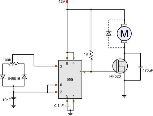
You can move your car in three different modes. 3 easy to build speed controller circuits for DC motors are presented here one using MOSFET IRF540 second using IC 555 and the third concept with IC 556 featuring torque processing. These kinds of motors are very commonly found in hobby RC vehicles and in multi-rotor drones.
HT12D decoder Pin Out L293D motor driver Pin Out RF receiver module Pin Out Wire the circuit as per the above receiver schematic. Initially when no IR beam is falling on sensor TSOP1738 the relay remains de-energised and the toy car doesnt move. The BEC is a separation of the electronic speed control that will transmit power back to your receiver after that to servos.
By using that gamepad you can control the Bluetooth car. The remote controller sends out a encoded radio-frequency RF signal to the RC car. Depend-ing on the position of the handles or rotation knobs a pulse of 1 to 2 msec with a rep-etition of 50 Hz will become available in the.
A remote control transmits eg. It uses simple integrated circuits IC and it is controlled wirelessly by a remote controller. A circuit which enables a user to linearly control the speed of a connected motor by rotating an attached potentiometer is called a motor speed controller circuit.
Take out a multimeter put it into diode mode and try to connect one end of the switch to ground. In these projects you will learn the interfacing of sensors coding for robots and cars and many other things. Working of the circuit is simple.
RPMs per volt Enter the LiPo cells in series Enter the amount of teeth for the pinion gear and spur gear Enter the amount of teeth for the pinion hear and spur gear of the differential Enter the diameter of the tires in mm. In that application there is a gamepad. RC Speed Controller Circuit OPERATION RC PROPORTIONAL CONTROL - INPUT SIGNAL Most proportional control systems follow a standard format.
L255rR-255r On this command the left engine will rotate back and forward right forcing a car to rotate around its axis counterclockwise. HOW TO MAKE MOTOR DRIVER CIRCUIT FOR RC CARHi friends in this video i have made a motor driver circuit for an rc car this is a four motor driver circuit made. Electric rc cars need an ESC electronic speed controller to work correctly.
When switch S1 is pressed the IR beam falls on TSOP1738 and its output goes low. ESC Design An electronic speed controller can be designed with three essential components like a voltage regulator BEC Battery Eliminator Circuit a Processer the switching includes FETs. Enter the Brushless Motor KV value.
Every RC vehicle or airplane or any other sort of machine needs an ESC to properly function. For model aircrafts speed cars ships and battery powered or life steam trains. As we power the ESP32s the Bluetooth module starts working and gets connected to a smartphone when you start Dabble App installed on it.
Brushless Electric Estimated Speed Calculator - RC Car Calculator. There are two LEDs in the receiver board. H1r Command is an additional channel to which you can connect for example lights sound etc.
Working of Bluetooth controlled RC car. If your going to go the route of cannibalizing an old rc car with 2 way radio steering servo receiver electronic speed control like i. On this command RC car will move forward and slightly rotated to the right as right engine rotates slowly left.
3 male to female jumper wires. Making the Receiver Circuit The receiver circuit consists of three ICs. The RC car decodes the signal and moves accordingly.
Most RC car radios have two channels because a car has two functions to control. To make Bluetooth control rc car you must have some hardware as I mention in the article and the connection according to the circuit diagram.
Esc Control For Brushless Motors Electronic Circuit Projects Circuit Projects Diy Cnc Router

How To Make An Universal Dc Motor Speed Controller Motor Speed New Electronic Gadgets Electronics Projects Diy

How To Make An Universal Dc Motor Speed Controller Grow Amis Motor Speed Electronics Mini Projects Circuit Board

555 Dc Motor Speed Control Motor Speed Circuit Diagram Electronic Circuit Projects
Pin On Ioji3

12 Volt Dc Motor Speed Controller Motor Speed Circuit Diagram Electronic Circuit Projects

Pwm With Forward And Reverse Finally Dc Motor Speed Controller Simple Circuit Youtube Remotecontrolboat Rc Remote Simple Circuit Remote Control

How To Make An Universal Dc Motor Speed Controller Motor Speed Electronic Circuit Projects Rc Circuit

Diy Regulator Brzine Dc Motora Dc Motor Speed Controller Youtube Motor Speed Electronic Circuit Projects Hobby Electronics

Simple Dc Motor Speed Control Circuit Wiring Diagram By Tech Bondhon Electronic Circuit Projects Motor Speed Circuit Projects
How To Build The Simplest Dc Motor Speed Controller Using Potentiometer And Mosfet Updated Motor Speed Electronics Mini Projects Electrical Circuit Diagram

How To Build The Simplest Dc Motor Speed Controller Using Potentiometer Motor Speed Electronics Mini Projects Electrical Circuit Diagram

Diy Mosfet Motor Controller Electronic Circuit Projects Radio Control Diy Circuit Projects

Pwm Motor Light Controller Electronics Basics Control Circuit Diagram

How To Make A Simple Dc Motor Speed Controller Youtube Motor Speed Motor Electric Circuit

Arduino Brushless Motor Control Tutorial Esc Bldc Howtomechatronics Arduino Arduino Projects Control

Joystick Controlled 2 4 Ghz Rc Car Using Arduino Arduino Circuit Projects Joystick

12 Volt Dc Motor Speed Controller How To Make Simple Diy Hacks Easy Way To Make Dc Voltage Controller 12 Volt Dc Mot Motor Speed Electronics Basics Motor

Arduino Brushless Motor Control Tutorial Esc Bldc Howtomechatronics Arduino Circuit Diagram Circuit


Post a Comment for "Rc Car Speed Controller Circuit"